Choosing the best 3D UV Laser Marking Machine in 2026 takes more than comparing wattage or advertised speed. Buyers need to test how consistently a system marks curved surfaces, fine text, and heat-sensitive materials. A sample part tells a clearer story than a polished brochure.
Grand View Research’s laser-marking market report points to continued growth in the broader sector. That trend is useful context, but it does not prove that every 3D UV system will suit your production line. The report covers laser marking overall, not this specific machine category. Compare verified specifications, application trials, warranty terms, and service support before deciding.
Prof. Reinhart Poprawe, a prominent laser-technology researcher and former director of Fraunhofer ILT, offers a useful expert lens on laser processing: material and process fit matter. Put that into a practical buying question: “Does the mark stay crisp without damaging the surface?” Check the answer on your actual parts, including edges and recessed areas. Then review cycle time and repeatability across multiple samples. Small variations matter.
This guide compares 3D UV Laser Marking Machine options using those checks. It also looks at marking quality, system configuration, usability, and support. Some specifications can be difficult to compare directly. That deserves caution, not guesswork. The right choice is the machine that meets your real production needs—not simply the one with the strongest headline claim.
What Is a 3D UV Laser Marking Machine?
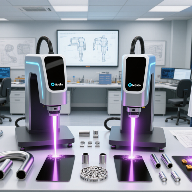
A 3D UV laser marking machine uses ultraviolet laser energy to create fine marks on materials while adjusting focus across changing surface heights. Many systems use a 355-nanometer source, though specifications vary. The “3D” feature usually refers to dynamic focus control, not printing a fully three-dimensional object. A flat-field machine focuses across a mostly level work area; a 3D system can compensate for curved or stepped surfaces.
This can help mark a small logo across a gently curved plastic housing or place text on different levels of a component. UV energy often supports precise, low-heat marking, but results depend on the material, coating, settings, and lens setup. A sample test matters. Even then, the first pass may look uneven, so operators should inspect contrast and edge quality before production. “3D” alone does not guarantee a better mark.
Tips: Check the maximum height range, focus accuracy, and compatible materials. Test the actual part, not just a flat sample. Keep the surface clean, and record settings that produce consistent results. One detail is easy to overlook: fixtures can affect focus.
Which Is the Best 3D UV Laser Marking Machine in 2026? - What Is a 3D UV Laser Marking Machine?
| Dimension | Typical Characteristics | What to Check | Why It Matters |
|---|---|---|---|
| What “3D UV” Means | A UV laser marker uses ultraviolet laser light, commonly at a 355 nm wavelength. A 3D configuration adds dynamic focusing to adjust the focal position across surfaces at different heights or angles. | Confirm that the system includes a compatible 3D scan head, dynamic-focus unit, and marking software—not just a UV laser source. | The 3D focusing system helps maintain a usable focus on contoured or uneven parts compared with a fixed-focus setup. |
| Laser Wavelength | UV marking systems commonly operate at 355 nm. Short-wavelength energy can be absorbed effectively by many materials and can support fine marking with limited heat-affected areas in suitable applications. | Request samples made from the exact material, color, coating, and surface finish used in production. | Marking results depend on the material and process settings; UV does not guarantee damage-free processing. |
| Laser Power | UV sources are available at different output powers. Higher power can improve throughput for some jobs, but it does not automatically produce a better mark or suit every material. | Compare measured results at the intended production speed, including mark contrast, edge quality, depth, and consistency. | Choosing power based on a production trial is more reliable than selecting a system by power rating alone. |
| 3D Working Area and Focus Range | The usable marking field and supported height variation depend on the scan head, optics, and configuration. A larger field can affect achievable spot size and marking performance. | Ask for the specified field size, working distance, focus range, and marking-quality results across the full area and height of your part. | A machine must accommodate the real part geometry—not just a flat test area or a stated maximum field. |
| Supported Materials | Depending on the material and settings, UV lasers can mark or process certain plastics, glass, ceramics, coated surfaces, and metals. Results vary significantly by material formulation and finish. | Test every production material and color. Check for readability, surface damage, discoloration, and durability after handling or cleaning. | A successful sample on one type of plastic or glass does not establish performance on another. |
| Marking Speed and Throughput | Actual cycle time depends on the artwork, material, required contrast or depth, focus movements, part handling, and inspection requirements. | Time a representative production job, including loading, positioning, marking, and unloading—not just the scan-head movement. | A practical throughput test gives a more useful comparison than a maximum speed specification. |
| Software and 3D Workflow | A 3D marking workflow may require surface or height data, correct focus compensation, and suitable import or job-preparation tools. | Check file compatibility, job setup, operator training, fixture alignment, and how the system handles curved or tilted parts. | Clear software and repeatable setup reduce programming time and help maintain consistent results. |
| Safety and Extraction | Laser safety requirements depend on the system configuration and installation. Marking can produce fumes or particles that may require suitable extraction. | Review the enclosure, interlocks, applicable safety documentation, risk assessment, and extraction needs for the materials being processed. | Safe operation requires a suitable installation and operating procedure; protective measures should be assessed for the actual work environment. |
| How to Choose the Best Fit | The best system is the one that meets the part’s geometry, material, mark-quality, cycle-time, and production requirements in a representative trial. | Compare sample quality, full-part focus performance, repeatability, workflow, safety provisions, service support, and total operating requirements. | There is no single best specification for every application; a documented production test is the strongest basis for selection. |
FAQS
It should keep focus consistent on curved or stepped surfaces. Check fine text near the center and edges.
Plastics, coated metals, glass, and ceramics can respond differently to UV marking. Use a sample with the same coating and finish as your part.
Check line width, contrast, edge sharpness, and heat effects under magnification. Look closely.
Test several positions around the curve. Small focus errors can make characters fuzzy or uneven.
No. Compare speed at an acceptable quality level, then check repeatability across multiple runs.
Ask about wavelength, pulse settings, working-field limits, file formats, height mapping, and setup time. Also check whether operators can adjust settings without guesswork.
Review the enclosure, interlocks, and fume extraction for your workspace. Ask how calibration is checked after maintenance; that step is easy to overlook.
Not necessarily. A larger field may reduce detail or need careful calibration. Match the machine to your parts, production pace, and operator experience. One sample can be misleading.
Conclusion
A 3D UV Laser Marking Machine uses ultraviolet laser energy and coordinated motion to create precise marks on objects with curved, angled, or uneven surfaces. Its short-wavelength beam can produce fine details with limited heat impact, making it suitable for applications where surface quality and legibility matter. Understanding how the laser, focusing system, and 3D positioning work together helps explain how the machine maintains consistent results across different surface shapes.
Choosing the best machine in 2026 depends on more than speed or resolution. Buyers should compare marking accuracy, working area, software and 3D scanning capabilities, ease of operation, maintenance needs, and overall production costs. They should also consider the materials to be marked, the shape and size of the parts, required output volume, and the desired mark quality. Matching these factors to real production requirements can help identify a reliable solution without paying for features that are unnecessary.