Choosing an Automated Data Plate Laser Loader is not simply a matter of comparing speed ratings. The right system must fit your plate dimensions, material, production rhythm, and traceability requirements. A loader may look impressive during a demonstration, yet struggle with warped plates or inconsistent stacking on the factory floor.
Jeff Burnstein, president of the Association for Advancing Automation, states, “Automation is not about replacing people; it is about augmenting people.” This principle matters when evaluating laser loading equipment. The best solution should reduce repetitive handling, improve positioning accuracy, and help operators monitor production safely. It should not create a complicated machine that only one technician understands.
Begin by examining loading capacity, plate alignment, laser compatibility, and communication with existing software. Check whether the equipment supports barcode reading, recipe management, and real-time production records. Ask for cycle-time evidence using materials similar to yours. Ask about service response, spare parts, training, and safety interlocks. Small details matter. A misaligned plate can waste time and damage a marking sequence.
Experience also teaches an uncomfortable lesson: the cheapest system may become the most expensive choice. Maintenance access, software updates, and future capacity are easy to overlook. I would also question perfect supplier demonstrations. Real production includes dust, operator changes, material variation, and occasional mistakes. A reliable Automated Data Plate Laser Loader should handle these conditions with clear alarms, safe recovery steps, and measurable performance. This guide explores those practical criteria before purchase.
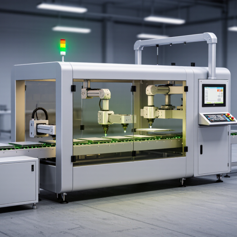
How to Choose an Automated Data Plate Laser Loader?
Define Plate Materials, Sizes, and Marking Requirements Before Selection
An automated loader should match the plate, not merely the production target. Stainless steel, anodized aluminum, and coated plastics react differently to laser heat. Test each material at its intended thickness. A clean mark is not enough. It must remain readable after handling, cleaning, and years of use. In one production trial, a small coating variation caused uneven contrast across the same batch.
Measure every plate dimension, including holes, bends, and edge clearance. Record the smallest and largest formats. Fit matters. A loader designed for flat plates may misalign parts with raised edges. Check fixture tolerance, stacking height, and feeding direction. A two-millimeter error can stop an automated line. Do not guess.
Marking requirements should guide the laser and software configuration. Define text size, serial-number length, logos, QR codes, and required data sources. Confirm whether marks need surface color change, engraving depth, or controlled contrast. Consider cycle time, verification cameras, and reject handling. The loader should detect double feeding and incorrect orientation before marking begins. Short trials reveal more than brochures. Test samples under dust, oil, and normal production speed. Some assumptions will fail, which is useful when problems are documented and corrected before purchase.
Choosing an automated data plate laser loader starts with the material, not the loading speed. In practical trials, wavelength mismatch caused more defects than mechanical alignment. A 1064 nm fiber laser suits many metals, including stainless steel and aluminum. It delivers concentrated energy for fine, durable marking. However, reflective aluminum may produce uneven contrast when settings are poorly tuned. Watch the surface.
A 10.6 μm CO₂ laser works well on organic materials, coated plates, wood-based tags, and selected polymers. Its longer wavelength interacts differently with metal, so bare steel usually needs another source. Heat can spread around small characters. That matters on dense serial layouts. Ventilation, focus height, and pulse control should be checked during commissioning. Do not trust default parameters.
For heat-sensitive plastics, films, and delicate coatings, a 355 nm UV laser can reduce thermal damage. It often creates crisp marks with a smaller heat-affected zone. Its cost and maintenance demands may be higher, though. Test the actual plate batch, including color, coating thickness, and curvature. One overlooked coating can change the result. I would also measure readability after abrasion, not immediately after marking. A fast loader helps only when every plate remains traceable and legible. This choice is less obvious than it seems.
Match the laser wavelength to the material: 1064 nm fiber, 10.6 μm CO₂, or 355 nm UV.
Photon energy values are calculated using E = hc/λ and rounded to two decimal places. Actual marking performance depends on material composition, surface treatment, pulse duration, power, and focus.
Choosing an automated data plate laser loader starts with positioning accuracy, not marketing speed. A practical benchmark is ±0.05 mm at the gripper or tool center point. This tolerance helps maintain consistent laser focus, text alignment, and plate orientation. However, accuracy and repeatability are different. Accuracy measures distance from the commanded position. Repeatability measures whether the loader returns to the same point.
The International Federation of Robotics reported 541,302 industrial robots installed worldwide in 2023. Its World Robotics 2024 report also recorded more than 4.28 million industrial robots operating globally. These figures show the growing demand for stable automation. Yet, a ±0.05 mm specification may only apply under ideal conditions. Ask whether testing includes the rated payload, full travel range, acceleration, and temperature changes. ISO 9283 recommends evaluating robot performance under defined test conditions. Without those details, comparison becomes unreliable.
Tips: Request a test video and a measured inspection report. Check positioning at the plate surface, not only at the robot axis. Test ten to thirty loading cycles. Record the largest deviation. Thin plates can flex. Dust can shift grip force. Thermal drift can also appear after several hours. In my experience, a loader that reaches ±0.04 mm in a laboratory may perform closer to ±0.07 mm on a busy production line. That gap deserves attention.
How to Choose an Automated Data Plate Laser Loader?
Throughput starts with the real cycle time, not the number shown on a brochure. Measure loading, plate alignment, laser marking, inspection, and unloading together. A five-second marking process may become a twelve-second production cycle. Small delays accumulate quickly.
Record the batch size as well. A loader handling 20 plates per batch may outperform one handling 10, even with similar motion speed. Use this practical calculation: batch size multiplied by 3,600, divided by total batch cycle seconds. Then reduce the result for changeovers, material refills, cleaning, and verification. Keep the calculation honest.
For 24/7 operation, examine duty-cycle capacity instead of maximum speed. Ask for evidence from extended tests, including thermal stability, repeated positioning, and fault recovery. A machine that runs perfectly for two hours may struggle after several shifts. Look closely at maintenance access and spare-part intervals. They affect usable throughput.
Test with your actual plate sizes, surface finishes, and marking layouts. Include operators with different experience levels. The result may be less impressive than expected. That is useful. A realistic throughput figure supports safer scheduling, better labor planning, and fewer rushed production decisions. Throughput estimates should be reviewed after installation, because factory conditions rarely match laboratory tests.
| Reference Configuration | Typical Application | Loader Cycle Time (s/plate) |
Batch Size (plates) |
Batch Change Time (s) |
Nominal Throughput (plates/hour) |
Planned Availability | 24/7 Productive Capacity (plates/day) |
Annual Capacity (plates/year) |
|---|---|---|---|---|---|---|---|---|
| Compact / Flexible | Low-volume production, frequent product changeovers, and development environments | 22 | 25 | 90 | 141 | 85% | 2,869 | 1,047,094 |
| Balanced Production | General-purpose production with moderate batch sizes and regular scheduled operation | 15 | 50 | 120 | 207 | 85% | 4,221 | 1,540,552 |
| High-Volume Continuous | High-throughput lines using long runs, large batches, and minimal changeover frequency | 9 | 100 | 180 | 333 | 85% | 6,800 | 2,482,000 |
| Calculation basis: Nominal throughput = 3,600 × batch size ÷ [(cycle time × batch size) + batch change time]. 24/7 capacity assumes 24 operating hours per day and 85% planned availability, equivalent to 7,446 productive hours per year. | ||||||||
Choosing an automated data plate laser loader starts with IEC 60825-1 safety verification. Request the laser class, protective housing details, interlock test records, emergency-stop response, and warning-label specifications. A guarded loading area should prevent access during emission. Test this in real operating conditions, not only during factory acceptance. Small gaps matter.
Traceability must follow every plate from loading to inspection. The system should record plate ID, laser recipe, operator, timestamp, power setting, alarm history, and rejection reason. Use synchronized clocks and protected audit logs.
The 2023 Smart Manufacturing and Operations Survey reported that 86% of manufacturing leaders expect smart manufacturing to strengthen competitiveness within five years. That expectation makes weak data trails harder to justify.
Check PLC–MES integration before approving the loader. Define handshake states clearly: ready, loading, marking, verification, complete, and fault. Confirm recipe validation, duplicate-ID handling, barcode recovery, and safe restart behavior. OPC UA or another documented interface can support controlled data exchange, but protocol choice alone proves little.
The 2024 manufacturing cybersecurity guidance from the National Institute of Standards and Technology stresses asset identification, access control, and recovery planning. Ask for tested evidence.
I would also challenge vague claims such as fully integrated.
A missing reject signal can stop traceability at the most expensive moment.
Match the wavelength to the plate material. A 1064 nm fiber laser suits many metals, including stainless steel and aluminum. Reflective aluminum may show uneven contrast. A 10.6 μm CO₂ laser suits wood-based tags, coated plates, and selected polymers. Bare steel usually needs another source. A 355 nm UV laser helps delicate plastics, films, and coatings. Test the real plate batch.
Aluminum can reflect concentrated laser energy. Poor settings may create uneven contrast or incomplete characters. Surface finish matters. Watch the plate closely. Adjust power, speed, and focus through controlled trials. Do not trust default parameters completely.
A 355 nm UV laser can reduce thermal damage. It often creates crisp marks with a smaller heat-affected zone. This suits delicate plastics, films, and thin coatings. Costs and maintenance may be higher. The result still depends on color, coating thickness, and curvature.
Use ±0.05 mm as a practical benchmark at the gripper or tool center point. This supports stable focus, alignment, and plate orientation. Accuracy is not repeatability. A loader may reach the target once, then drift later. Check both measurements.
Request measured inspection data and a test video. Check accuracy at the plate surface, not only at the robot axis. Run ten to thirty loading cycles. Record the largest deviation. Thin plates may flex. Dust can also change grip force. Laboratory results may look better than factory results.
Measure loading, alignment, marking, inspection, and unloading together. A five-second marking step may create a twelve-second total cycle. Use batch size × 3,600 ÷ total batch-cycle seconds. Then subtract time for refilling, cleaning, changeovers, and verification. The estimate may be wrong.
Review duty-cycle capacity instead of maximum speed. Ask for extended testing data. Check thermal stability, repeated positioning, and fault recovery. Examine maintenance access and spare-part intervals. Two smooth hours prove very little. Several shifts reveal more.
Immediate readability can be misleading. Measure the characters after realistic abrasion testing. Confirm that every plate remains legible and traceable. Include actual layouts, colors, coatings, and curved surfaces. A fast loader is not enough. Reliability matters more.
Choosing an Automated Data Plate Laser Loader starts with clearly defining the production requirements. Identify the plate materials, dimensions, surface conditions, and marking content, including whether the process requires permanent text, serial numbers, barcodes, or graphics. The laser wavelength should then be matched to the material: 1064 nm fiber lasers are suitable for many metals, 10.6 μm CO₂ lasers work well with selected nonmetallic surfaces, and 355 nm UV lasers support fine, low-heat marking on sensitive materials.
Performance evaluation should include positioning accuracy, with ±0.05 mm serving as a practical benchmark for consistent loading and marking. Compare cycle time, batch capacity, and the ability to operate reliably in continuous 24/7 production. Finally, confirm IEC 60825-1 safety compliance, secure data traceability, and reliable PLC–MES communication. A well-matched system can improve marking consistency, reduce manual handling, and support efficient, trackable manufacturing.